Sloan Digital Sky Survey (SDSS) Multi-Object Fiber-Fed Spectrographs
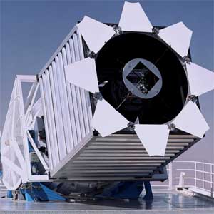
SDSS 2.5 m Telescope
The Sloan Digital Sky Survey is the most ambitious astronomical survey project ever undertaken. The original survey goal was to map one quarter of the entire sky, determining the position and absolute brightness of more than 100 million celestial objects. It measured the distance more than a 700,000 galaxies and quasars. The engineers at JHU, in collaboration with Johns Hopkins Astronomers, designed and built the SDSS multi-object fiber spectrographs, which facilitate these distance measurements.
The Department of Physics and Astronomy was responsible for the following tasks:
Instrument optical design
Optomechanical design of spectrographs
Fabrication and assembly of spectrographs
Design and assembly of the control electronics
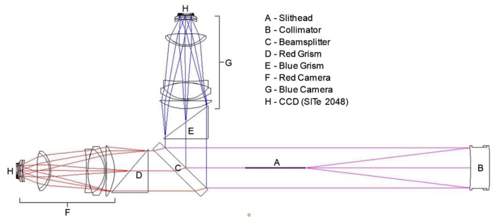
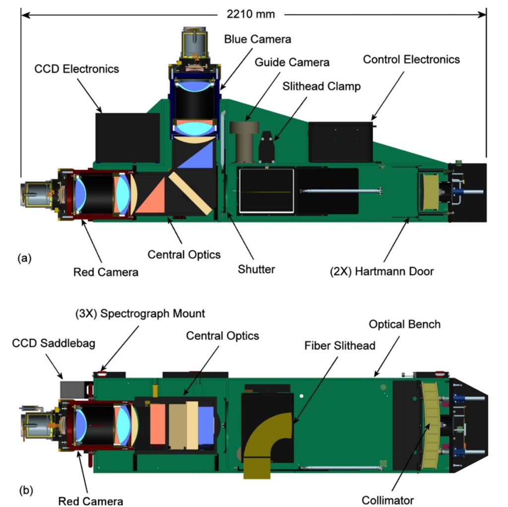
Optical layout of the SDSS spectrographs. Light enters each spectrograph through 320 180 μm diameter fibers, which terminate at a curved slit plate mounted inside the slithead. The slit plate positions the fiber ends on a radius concentric with the spherical collimating mirror, which operates at f/4 and produces a 160 mm diameter beam. The 45◦ dichroic beamsplitter reflects the blue portion of the bandpass (λ < 6000 Å) and transmits the red wavelengths (λ > 6000 Å). Immediately after the beamsplitter in each channel is a grism, consisting of a right angle prism with a transmissive surface-relief grating replicated on the hypotenuse. The dispersed light exits the grisms and enters all-refractive, eight-element, f/1.5 cameras. Each camera contains a single SITe 2k × 2k CCD with 24 μm pixels. The camera demagnification from f/4 to f/1.5 produces fiber images that are just under 3 pixels in diameter, resulting in 3 pixel tall spectra on the detector.Section views showing the optomechanical design of the SDSS spectrographs. The T-shaped optical bench is an enclosed aluminum (6061-T6) weldment with precision-machined interfaces to locate all five opto-mechanical subassemblies: the fiber slithead, the collimator, the central optics, and a the red and blue channel cameras. One of the two spectrographs also supports the guide camera. Electronics control chassis mount to the external walls of the bench. Three kinematic mounts on the top of the bench interface to the back of the Cassegrain instrument rotator.